Optical pattern formation
|
|
Shortcuts to projects in optical pattern formation:
|
Introduction
What is the reason that an initially homogeneous system evolves spontaneously
into a modulated, "structured" state? This intriguing question arises in
many sciences, in nature as well as in the laboratory. Spontaneous self-organization
phenomena in space and time are also ubiquitous in optical systems in which
intense laser beams interact with a nonlinear medium, i.e. a medium in
which the optical properties (refractive index or absorption coefficient)
depend on the intensity of the incident light. The interplay of spatial
coupling by diffraction and nonlinearity is responsible for the pattern
formation. It is highly fascinating that the properties of structures in
such different regions of science like hydrodynamics, chemical reactions,
gas discharges and optics possess remarkably universal aspects, and optics
is beginning to promote the knowledge on dissipative patterns by demonstrating
phenomena not known before. Therefore the investigation of optical patterns
is an important topic of interdisciplinary research using equipment of
technical relevance and might on the other hand form the basis for future
all-optical data processing.
Nonlinear effects occur in many media and in many different configurations.
Concerning the medium, we focus on experiments using sodium vapor. The
nonlinearity is due to optical pumping. Beside
technical advantages (high optical quality, easy variation of parameters
over a broad range, high resonant nonlinearity) the benefit of using an
atomic vapor is that the equations governing the light-matter interaction
can be derived directly from quantum mechanics via the density matrix approach.
Regarding the investigated configurations, investigations have been done
in most of the situations in which spatial optical structures are known
to occur. These are
The present focus is on the single-mirror feedback system since it is conceptually
very simple.
The Lab
A view to the lab
Here you can see some random pictures from the optical table within the
lab on which our experiments were performed.
 Picture 1: Shows the dye laser in the background. To the left
you see the stabilizing unit for the laser frequency. Picture 1: Shows the dye laser in the background. To the left
you see the stabilizing unit for the laser frequency. |
 Picture 2: To the left you see the mirror mount that brings
the laser beam to the constant height of 5 cm above the table. On the right
hand of that a part of the beam is coupled into an optical fibre (orange
coated) in order to measure the optical frequency with it. Picture 2: To the left you see the mirror mount that brings
the laser beam to the constant height of 5 cm above the table. On the right
hand of that a part of the beam is coupled into an optical fibre (orange
coated) in order to measure the optical frequency with it. |
 Picture 3: Shows the last part of the way of the beam, where the
beam quality is enhanced by spatial filtering. After that the beam is lifted
again to the height of the vapor cell which is surrounded by 3-dimensional
Helmholtz-coils. Picture 3: Shows the last part of the way of the beam, where the
beam quality is enhanced by spatial filtering. After that the beam is lifted
again to the height of the vapor cell which is surrounded by 3-dimensional
Helmholtz-coils. |
|
Main Equipment
-
argon ion laser 15 W (Spectra Physics 2030-15)
-
frequency stabilized ring dye laser (Spectra Physics 308D)
-
intensified CCD-camera Proxitronic HF4 S 5N (gate duration downto 5 ns)
-
trigger logic for slow-motion pictures of repetive fast phenomena with
a time resolution of 100 ns (video-sampling
method)
-
CCD-camera Pulnix TM-765 (glassless, selected for laser beam analysis)
-
data acquisition and image processing system based on LabView (National Instruments)
-
wavemeter (accuracy 500 MHz absolute, 200 MHz relative)
-
digital oscilloscope LeCroy 9400 (175 MHz)
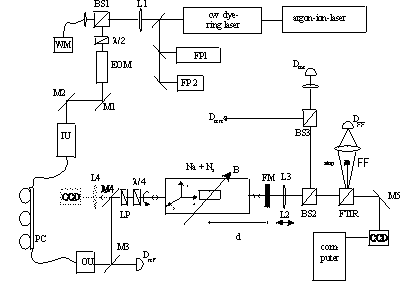
Detailed Experimental Setup
The setup can be schematically divided into four parts:
-
the laser system itself,
-
the preparation of the laser beam for the experiment,
-
the sodium cell, and
-
the detection system.

The purpose of the beam preparation section is to provide a well controlled
input beam for the experiment. This includes spatial filtering to ensure
a smooth and rotationally symmetric beam profile, the control of the polarization
state and means for power stabilization and ramping. The most important
part of the detection system are CCD-cameras which record two-dimensional
images of the intensity distribution in real space inside the vapor (near
field) and - in the back focal plane of a lens - simultaneously its Fourier
spectrum (far field). This allows a complete characterization of the field.
The next figure shows the complete setup as it was mounted for the investigation
of the patterns with circularly polarized excitation (click
here for references).
 (click on the image to get a better view)
|
|
L lens, BS beam splitter,
FP Fabry-Perot interferometer,
IU, OU fiber coupling units,
M mirror,
EOM electro-optical modulator,
lambda/4 , lambda/2 retardation plates,
D detector (photodiode),
CCD charge-coupled device camera,
FTIR variable beam splitter based on frustrated total internal reflection,
FM feedback mirror (R=0.915),
B system of three orthogonal pairs of Helmholtz coils.
|
The Team
-
HDoz Dr. Thorsten Ackemann
-
Dipl.-Phys. Florian Huneus
-
Dipl.-Phys. Matthias Pesch
-
Dipl.-Phys. Jens Schüttler
-
Jens-Uwe Schurek
- Former group members: Dr. Andreas Aumann, Dipl.-Phys. Burghard Berge, Dipl.-Phys. Monika Bölscher,
Dipl.-Phys. Marc Feldmann, Dipl.-Phys. Benedikt Giese, Dr. Edgar Große Westhoff, Dr. Ramon Herrero,
Dipl.-Phys. Andreas Heuer, Dipl.-Phys. Volker Kneisel, Dr. Yu. A. Logvin, Dipl.-Phys. Daniel Rudolph,
Dr. Burkhard Schäpers, Dipl.-Phys. Jens Seipenbusch, Dipl.-Phys. Michael Tegeler
|

